


Robotic Fiber Winding
Project Overview & Design
The focus of this investigation was the design of a structure that leverages the use of 6-axis robotic arms for its production. Carbon and glass fiber composites were chosen as a material reference for a structure with coreless filament winding (CFW).
A pedestrian bridge was proposed as an example use case. Its global geometry follows an anticlastic surface with a walkable slope in the long and short directions. Forty-eight double layered modules conform to the structure of the bridge. Each one consists of 3 fiber layers with different syntax types for specific structural purposes, leading to a doubly curved surface.
Path Planning
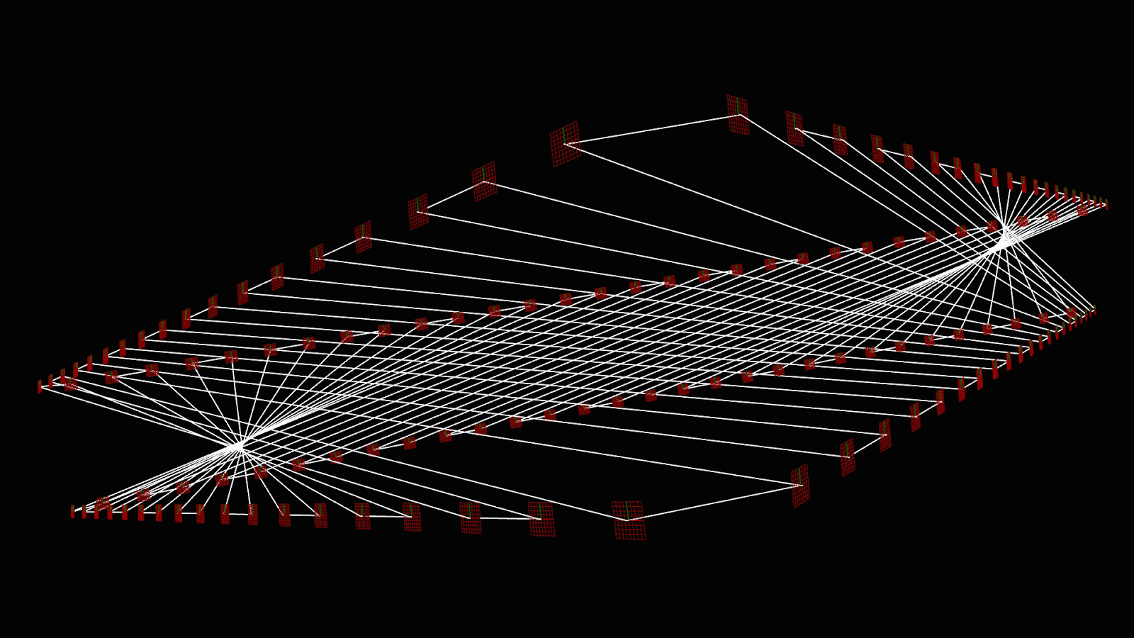
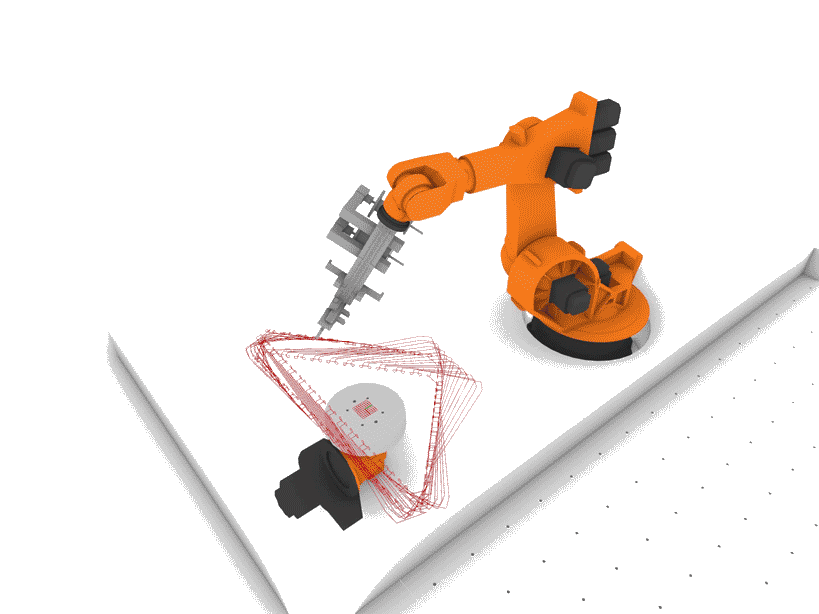
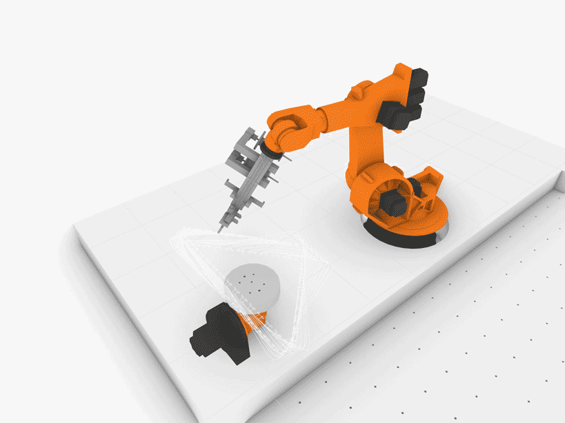
Fabrication paths were planned for a KR 125 KUKA robot with a fiber-laying end effector and for a two-axis KUKA DKP positioner for orienting the module’s frame. The additional axis of the DKP increased the fabrication space of the robot by focusing the general position of the end effector within a controlled range, increasing the allowed scale of the modules.
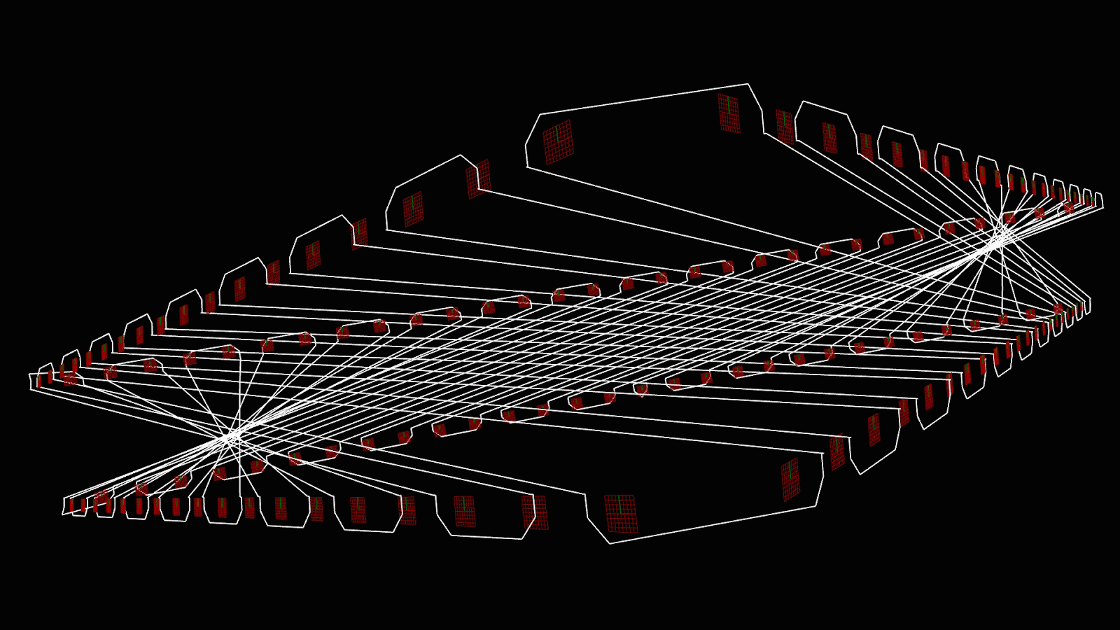
The “body” layer of the largest module was used for testing the path planning. Every path was generated following the layer’s syntax and adding steps for the anchoring of fiber. The resulting path from the coordinated movement between the robot and positioner was tracked, leading to a non-linear and counterintuitive motion.